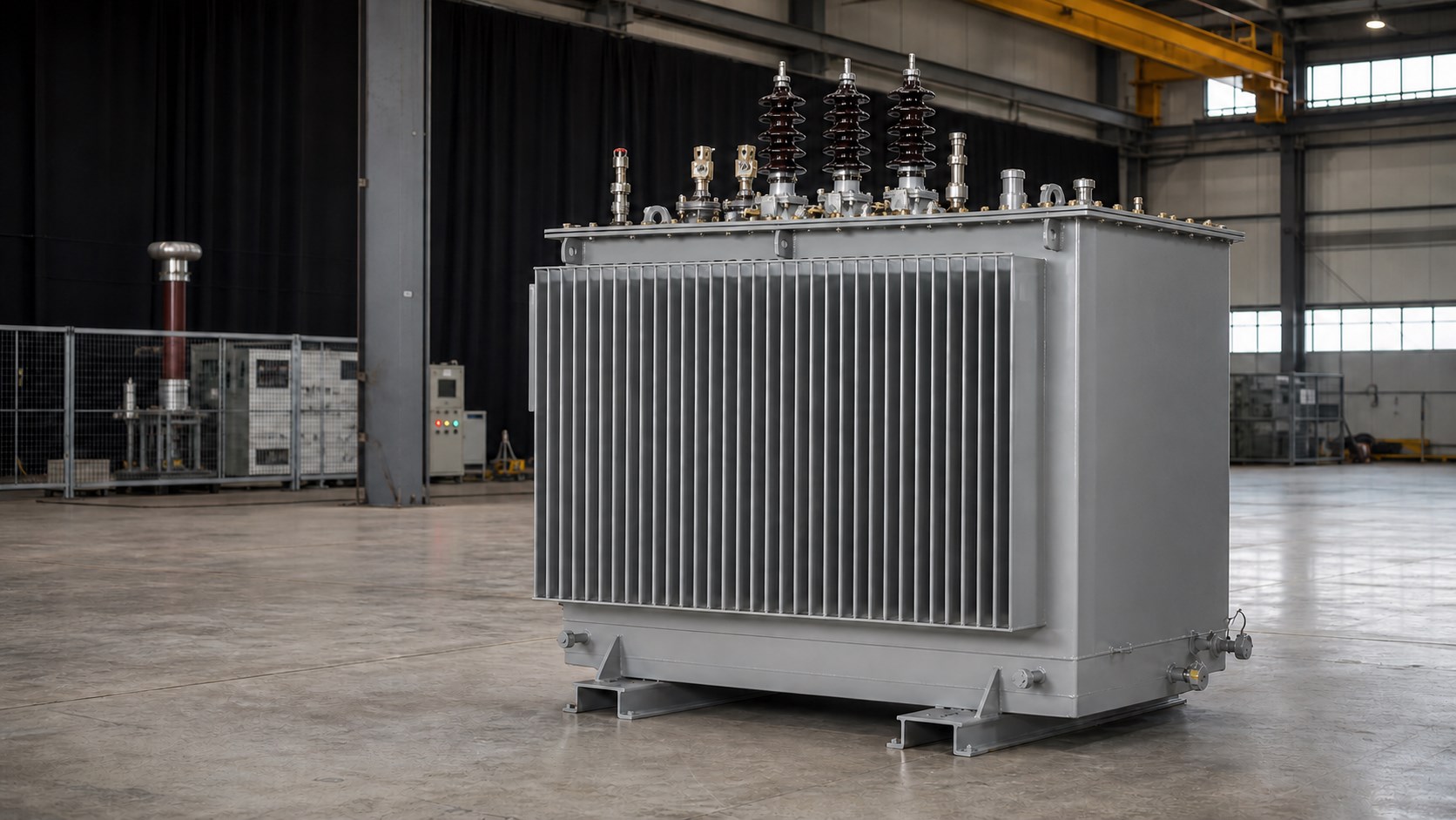
Build control starts before final assembly
The delivered condition of a hermetically sealed transformer is shaped by electrical design, active-part manufacture, insulation processing, tank construction, weld quality, gasket selection, accessory interfaces and assembly practice. Final assembly is where many manufacturing stages meet; an earlier dimensional, material or process deviation may later appear as temperature-rise concerns, interface mismatch, unstable sealing or abnormal test data.
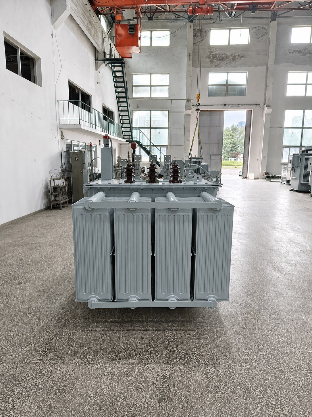
- 01
Technical data frozen
Confirm rating, voltages, frequency, vector group, impedance, losses, insulation level, environment, interface dimensions and accessory configuration. Unapproved data does not pass directly into subsequent manufacture.
- 02
Active part and insulation prepared
Manufacture and inspect the core, windings, leads and insulation structure against the design documents, with attention to conductor specification, turns, clearances, connection positions, clamping condition and cleanliness.
- 03
Tank and corrugated structure
Produce the tank, corrugated structure, reinforcements, interfaces and welds around oil volume, cooling, internal pressure and mechanical-strength requirements. Key dimensions and the sealing boundary are checked before final assembly.
- 04
Assembly and interfaces rechecked
Install the active part, bushings, tapping device, valves and monitoring or protection accessories; recheck HV/LV direction, phase sequence, centres, flanges, fasteners and customer connection interfaces.
- 05
Insulation treatment and oil filling
Complete active-part treatment, vacuum processing, oil filling and settling as required by the product construction and process documents. Specific process parameters are established by the product design and manufacturing files.
- 06
Sealing inspection and factory tests
Inspect welds, flanges, bushings, valves, gaskets and the tank, then complete and record the electrical tests required by the applicable standard and project documents.
Sealing reliability comes from the complete boundary, not from a single gasket
In a hermetically sealed transformer, every point connected to the insulating oil or the tank's internal space belongs to the sealing boundary. In addition to tank welds and flanges, this includes bushing mounting faces, the tapping device, valves, temperature or pressure interfaces, structures around earthing points and other accessory connections.
Sealing control must consider material compatibility, gasket compression, contact-surface condition, tightening sequence, temperature cycling, internal-pressure change and transport vibration. Passing one inspection does not replace sound structural design and repeatable assembly, so sealing must be controlled through design, manufacture, assembly and inspection.
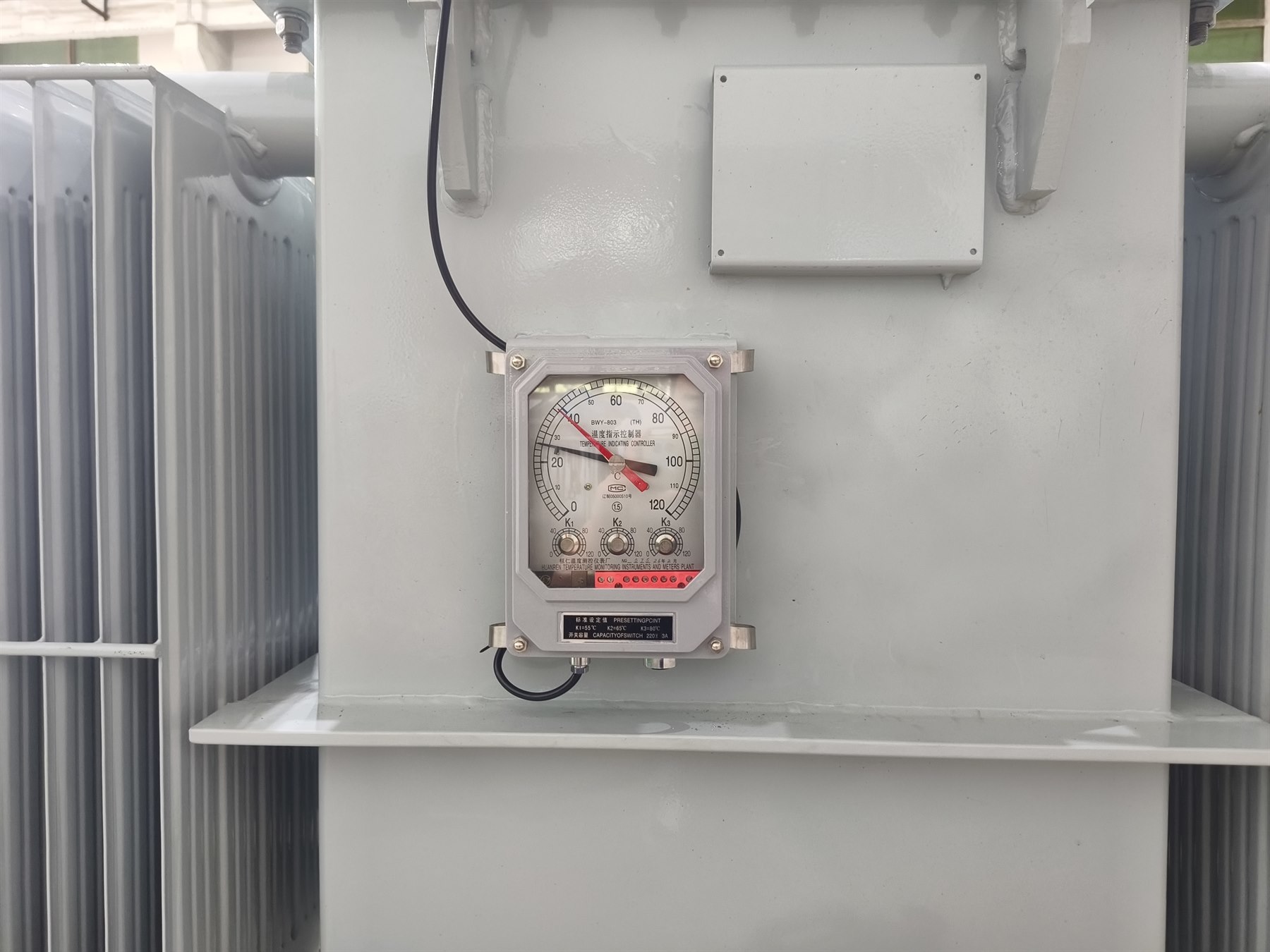
- 01Weld continuity and visible condition
- 02Flatness and cleanliness of flanges and sealing faces
- 03Gasket specification, position and compression condition
- 04Assembly condition of valves, bushings and accessory interfaces
Factory tests confirm whether the transformer has reached the agreed delivery condition
The test programme is determined by voltage class, rating, applicable standard and technical agreement. Routine tests confirm principal electrical parameters and insulation condition; type tests, special tests and third-party witnessing must be separately defined in the contract or project documents.
Winding resistance
Measure the DC resistance of each phase and the phase-to-phase variation to provide data on connection condition, conductor continuity and manufacturing consistency.
Voltage ratio, polarity and vector group
Confirm voltage ratio at the specified tapping positions, phase relationship, polarity and vector group against the approved design.
Insulation resistance and condition
Check insulation between windings and earth and between windings using the applicable method, supporting the assessment before dielectric testing and delivery.
No-load current and loss
Measure no-load current and no-load loss under the specified test conditions to check the core, excitation condition and design data.
Load loss and short-circuit impedance
Measure load loss and short-circuit impedance to verify winding, conductor and impedance data against the project agreement.
Applied and induced voltage withstand
Complete the required withstand tests according to the insulation level and applicable standard to verify insulation to earth, between windings and between turns.
Sealing and leakage inspection
Inspect the tank, welds, flanges, bushings, valves and accessory interfaces to confirm that no abnormal leakage affecting delivery is found under the specified inspection conditions.
Accessories and functional checks
Check the type, installation and basic functional state of tapping positions, temperature, pressure, oil-level, terminal, earthing and other agreed accessories.
NOTEThese are descriptions of common test items, not a fixed list for every transformer. Actual tests, methods, acceptance criteria and witness requirements follow the applicable standard and technical agreement.
In replacement projects, rating is often not the part that causes trouble
Existing equipment usually has to be replaced within a limited outage and fixed installation boundary. Even when old and new units share the same rating, voltage and model designation, differences in dimensions, fixing holes, phase sequence, bushing centres or accessory interfaces can prevent direct connection. Interface review must therefore be completed before design and production, not after the transformer reaches site.
SUBMIT NAMEPLATE & SITE DIMENSIONS- 01Original equipment nameplate data
- 02Foundation dimensions and fixing holes
- 03HV/LV bushing positions and centre distances
- 04Busbar or cable connection method
- 05Phase sequence and outgoing direction
- 06Overall height and electrical clearances
- 07Lifting points, transport route and doorway dimensions
- 08Temperature, pressure, protection and secondary terminals
- 09Earthing position and site-work boundary
Project documents connect design, manufacture, acceptance and site installation
Manufacturing confirmations and tests should create traceable records. The delivery-document scope is determined by the contract and project requirements and may include approved data sheets, arrangement and nameplate drawings, test reports, packing and accessory lists, installation instructions and other agreed documents.
Approved documents
Technical agreement, data sheet, interface conditions and approved drawings.
Manufacturing records
Key dimensions, process checks and inspection records required by the project.
Test documents
Factory-test results, witness records and other test information required by contract.
Delivery documents
Nameplate, general arrangement, packing list, accessory information and installation instructions.
NOTEThe document set is not identical for every project; its final scope follows the contract and agreed project requirements.
New build, replacement or special load?
Provide rating, voltage, load type, installation environment, interface dimensions and applicable standard. For replacement projects, also send the original nameplate, drawings and site photographs so electrical data, arrangement and installation conditions can be reviewed.